5. ESonix Model
5.1. Download our latest model template
- basic template: http://www.aero-sonix.com/static/support/ESonix_template.xlsx
- basic template: http://www.aero-sonix.com/static/support/ESonix_template_dynamical.xlsx
5.2. What is a decompression model?
Nothing more than a bunch of volumes connected through vents! You can figure your A/C Layout:
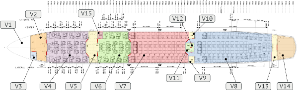
Fig. 5.1 Aircraft Layout
As being a network of volumes:
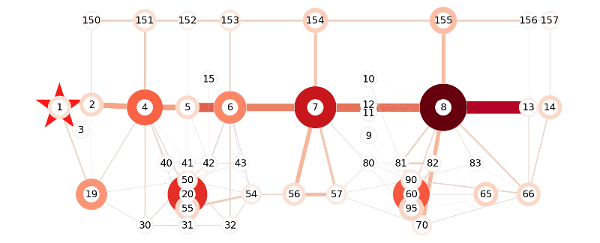
Fig. 5.2 Aircraft Model
Creating a model is just matter of describing this network, in terms of volumes and vents.
Additionally, some data about load cases need to be provided. By load case, we mean opening to ambient.
How to fill the model template
This document describes how to build a reliable model. As of now, model are described via an excel spreadsheet embedding at least three tabs:
- Load_Cases (mandatory)
- Volumes (mandatory)
- Connections (mandatory)
Additionally, the following tabs may be included:
- Dyn_Attributes (optional)
Warning
tabs name and columns headers are case-sensitive.
Note
Additional tabs are allowed and will be ignored.
5.3. tab “Load_Cases”
This tab is mandatory.
Load cases define the different opening holes to simulate. Besides the opening holes themselves, load cases also define the opening hole’s discharge coefficient and the differential pressure.
Parameters
| description | default | units | |
|---|---|---|---|
| id | Load Case ID | mandatory | no units |
| vol_i | ID of Exploded Volume(s) | mandatory | no units |
| opening_hole | Raw opening area | mandatory | [m^2 | in^2] |
| cp | Discharge coefficient | mandatory | no units |
| altitude | Flying altitude | blank | [m | in] |
| pressure_coeff | Aircraft pressure coefficient | 0 | no units |
| mach_number | Aircraft mach number | 0 | no units |
| p_atm | Atmosphere pressure value | blank | [bar | psi] |
| t_cabin | Cabin initial temperature | 296 | [K] |
| p_cabin | Cabin initial pressure | mandatory | [bar | psi] |
| label | Load Case label | mandatory | no units |
Load_Cases/id
flags:
- Type: Int in range [1; +∞]
- Default: None
- Mandatory: True
- Unique: True
Short description:
Load Case ID [no units]
Load_Cases/vol_i
flags:
- Type: Str
- Default: None
- Mandatory: True
- Unique: False
Short description:
ID of Exploded Volume(s) [no units]
The vol_i parameter refers to the exploded volume, the one beeing
connected to the ambient. Two kinds of parameters are allowed:
- and integer refering to an existing volume ID
- a string “<id1> + <id2> [ + <idn>...] refering to existing volume IDs
When volume IDs are summed, ESonix will automatically merge those volumes and reroute connections.
Load_Cases/opening_hole
flags:
- Type: Float in range ]0; +∞]
- Default: None
- Mandatory: True
- Unique: False
Short description:
Raw opening area [m^2] or [in^2]
Opening hole is defining the connection to the ambient. It is defined by FAR25.365e as a function of the fuselage diameter. You can use the toolbox to calculate it: http://www.aero-sonix.com/toolbox/opening_hole
Load_Cases/cp
flags:
- Type: Float in range [0; 1]
- Default: None
- Mandatory: True
- Unique: False
Short description:
Discharge coefficient [no units]
Load_Cases/altitude
flags:
- Type: Float in range [0; +∞]
- Default: nan
- Mandatory: False
- Unique: False
Short description:
Flying altitude [m] or [in]
The interesting value for a load case is mainly the differential pressure between the cabin pressure and the ambient pressure. Knowing the cabin pressure from aircraft manuals, or taking conservatively one atmosphere, the ambient pressure is still missing.
This ambient pressure can be calculated from a “standard atmosphere” at a given altitude. Such a tool is provided in the toolbox: http://www.aero-sonix.com/toolbox/by_altitude .
Load_Cases/pressure_coeff
flags:
- Type: Float in range [0; +∞]
- Default: 0
- Mandatory: False
- Unique: False
Short description:
Aircraft pressure coefficient [no units]
Load_Cases/mach_number
flags:
- Type: Float in range [0; +∞]
- Default: 0
- Mandatory: False
- Unique: False
Short description:
Aircraft mach number [no units]
Load_Cases/p_atm
flags:
- Type: Float in range [0; +∞]
- Default: nan
- Mandatory: False
- Unique: False
Short description:
Atmosphere pressure value [bar] or [psi]
Load_Cases/t_cabin
flags:
- Type: Float in range [0; +∞]
- Default: 296
- Mandatory: False
- Unique: False
Short description:
Cabin initial temperature [K]
Load_Cases/p_cabin
flags:
- Type: Float in range [0; +∞]
- Default: None
- Mandatory: True
- Unique: False
Short description:
Cabin initial pressure [bar] or [psi]
Load_Cases/label
flags:
- Type: Str
- Default: None
- Mandatory: True
- Unique: False
Short description:
Load Case label [no units]
Preprocessing
Besides the usual units conversions, ESonix will process load cases as follows:
If p_atm is not given, Atmospheric pressure will be calculated by altitude,
and optionnally mach_number and pressure_coeff.
Merged Load Cases
A special attention is taken by ESonix to handle automatically and transparently the merged load cases.
If ``raw_merging`` option is off (as set by default), when the explosion occurs in some (two or more) merged volumes, (cf. LC_vol_i parameter), ESonix will internally change the provided model by cancelling highest IDs merged volume(s). To do so, ESonix will sum all the merged volumes, change the lowest ID volume to match the new volume summed, and cancel the rest of the merged volumes.
For example, let say a load case merge volumes 1 and 3, ESonix will change volume 1 (lowest ID) such as its volume’s value match the sum of volume 1 and volume 3. Esonix will then cancel volume 3.
More over, ESonix will also automatically reroute connections to match the new layout, as explained in Fig. 5.3.
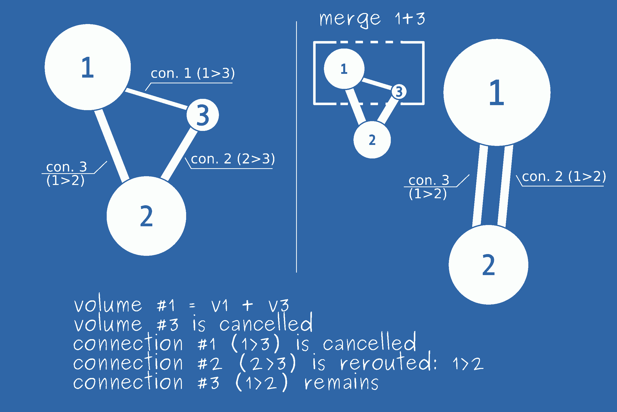
Fig. 5.3 Merging internal behaviour
Once the model is reinitialized (don’t forget to check the analysis logs to check what ESonix did!), calculations are performed using the new modified models. When storing results on disk, ESonix will then map the results (new volumes, new connections) to regular existing volumes and interfaces, such as results data mapping will be transparent to the user.
As an illustration for interface 2/3 is:
- \(P_3(t)=P_1(t)\)
- \(T_3(t)=T_1(t)\)
- \(\Delta_{P_{2(2>3)}}(t)=-\Delta_{P_{2(1>2)}}(t)\)
- \(\dot{m}_{2(2>3)}(t)=-\dot{m}_{2(1>2)}(t)\)
- and so on...
Note
The negative sign for \(\Delta_P\) and \(\dot{m}\) comes with the inversion of the connection: [2>3] = -[3>2]
User would therefore have a transparent access to \(\Delta_{P_{2/3}}\) although this interface does not exist for such a merged load case.
If ``raw_merging`` option is on, ESonix will not remap values and results would therefore present raw results, as calculated by ESonix.
Note
The raw_merging option is new starting from version 2.3. Previous
ESonix versions were showing results as if this option was “on”, therefore,
previous ESonix version were showing raw values.
5.4. tab “Volumes”
This tab is mandatory.
Volumes are the base parameters for a model decompression. They act as a tank of air. This air has a given pressure and temperatures at initial conditions, when t=0 sec.
As soon as one of the volume is connected to the ambient, the air located in the different volumes will be sucked by the ambient, leading to pressure on partitions.
Parameters
| description | default | units | |
|---|---|---|---|
| id | Volume ID | mandatory | no units |
| label | Volume label | mandatory | no units |
| deck | Deck Location | mandatory | no units |
| group | Group (sub-deck) identification for Unified Model | blank | no units |
| sta | Station | mandatory | [m | in] |
| rbl | RBL | mandatory | [m | in] |
| volume | Volume (size value) | mandatory | [m^3 | in^3] |
| deor | Deck Explosion Occupation Rate | 0.0 | no units |
| veor | Volume Explosion Occupation Rate | 0.0 | no units |
Volumes/id
flags:
- Type: Int in range [0; +∞]
- Default: None
- Mandatory: True
- Unique: True
Short description:
Volume ID [no units]
Volumes/label
flags:
- Type: Str
- Default: None
- Mandatory: True
- Unique: False
Short description:
Volume label [no units]
Volumes/deck
flags:
- Type: Int in range [-1; 2]
- Default: 0
- Mandatory: True
- Unique: False
Short description:
Deck Location [no units]
The mandatory deck parameter is used for organizing the results only and
has no effects on calculations themselves. An integer is to be provided as per
deck location, knowing by default:
deck==-1: volume located in the cargodeck==0: volume located at the main deckdeck==1: volume is a ceiling compartmentdeck==2: volume is on the second deck (in case of dual deck body)
Volumes/group
flags:
- Type: Int in range [-∞; +∞]
- Default: nan
- Mandatory: False
- Unique: False
Short description:
Group (sub-deck) identification for Unified Model [no units]
Volumes/sta
flags:
- Type: Float in range [-∞; +∞]
- Default: 0
- Mandatory: True
- Unique: False
Short description:
Station [m] or [in]
Volumes/rbl
flags:
- Type: Float in range [-∞; +∞]
- Default: 0
- Mandatory: True
- Unique: False
Short description:
RBL [m] or [in]
Volumes/volume
flags:
- Type: Float in range ]0; +∞]
- Default: None
- Mandatory: True
- Unique: False
Short description:
Volume (size value) [m^3] or [in^3]
Volumes/deor
flags:
- Type: Float in range ]-1; 1[
- Default: 0.0
- Mandatory: False
- Unique: False
Short description:
Deck Explosion Occupation Rate [no units]
DEOR stands for “Deck Explosion Occupation Rate” and defines how the volume is reduced when the explosion occurs somewhere in the same deck as the given volume. For example, this parameter is useful to initialize the cargo volumes with container inside when explosion occurs in the cargo.
Volumes/veor
flags:
- Type: Float in range ]-1; 1[
- Default: 0.0
- Mandatory: False
- Unique: False
Short description:
Volume Explosion Occupation Rate [no units]
VEOR stands for “Volume Explosion Occupation Rate” and defines how the volume is reduced when the explosion occurs in the volume itself.
See also
Tutorial #4 uses “VEOR” parameter in the section Unified model.
Preprocessing
Right before the actual run is solved, the model the user uploaded is preprocessed. For the volumes, it consists in setting blank cells to default values as defined in Volumes parameters.
Common examples
Volume reduction for a cargo compartment using DEOR
Volumes are really easy to idealize. Nevertheless, we will illustrate the use
of the DEOR parameter.
A regular LD-6 cargo container has an internal volme of 8.9m³.Let say that a cargo compartment has a volume of 25m³ and can therefore welcome two containers, as shown in Fig. 5.4.
It may be interesting to simulate the A/C with cargo empty for an explosion occuring in the cabin, and cargo occupied for an explosion in the cargo. Instead of creating two models, run two analysis and compare them, it is more convenient to inform ESonix of the expected behavior.
Setting DEOR will inform ESonix that, when the explosion occures in the cargo,
then the volumes of the cargo should be reduced by the DEOR factor.
If DEOR is null or blank, no reduction will therefore be applied.
In the current example, the volume occupied by the two containers is \(8.9 \times 2 = 17.8m^3\). Assuming that the both containers are full, the volume of air available is therefore \(25-17.8=7.2m^3\). The initial volume of air is therefore reduced by the DEOR coefficient \(DEOR=1 - \frac{7.2}{25}=0.712\)
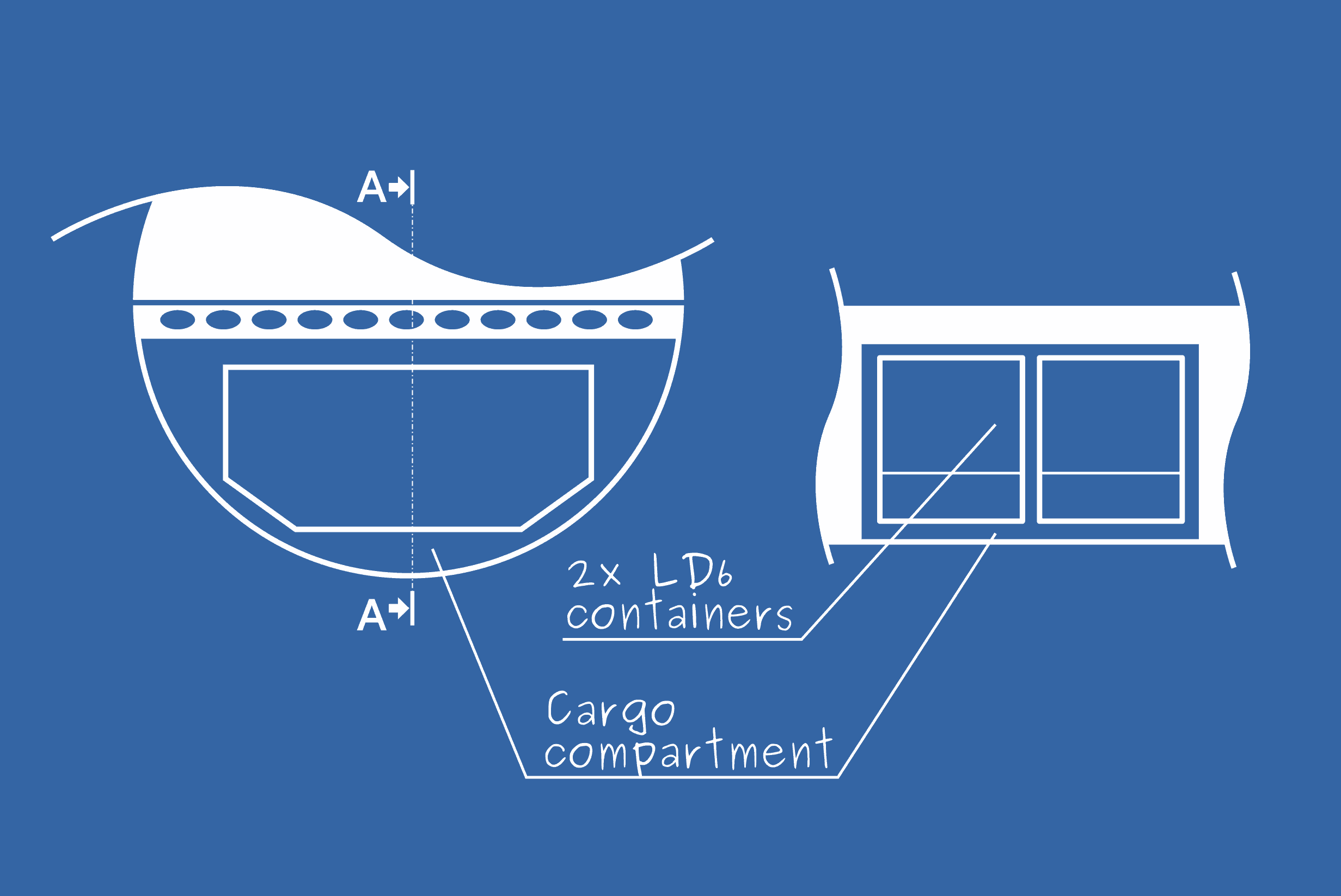
Fig. 5.4 Cargo compartment with two LD6 containers
| Column | User input | Preprocess | Actual input |
|---|---|---|---|
id |
9 | 9 | |
volume |
25 | 25 | |
label |
“cargo example” | “cargo example” | |
deck |
-1 | -1 | |
sta |
5 | 5 | |
rbl |
0 | 0 | |
deor |
0.712 | 0.712 | |
veor |
Default to zero | 0 |
5.5. tab “Connections”
This tab is mandatory.
A connection is connecting two volumes between them. Its geometry and behaviour will define how the mass of air in those volumes will be exchanged between them.
Basically, a connection always connect two volumes (aka vol I and vol J) and is therefore located at an interface.
When defining a connection, take care to always set volume I ID to the lowest ID of both volumes.
Example: let say you have two volumes to connect, ID2 and ID7, Volume I will always be volume ID2 and Volume J will always be volume ID7.
See also
Tutorial #2 is dedicated to decompression features whereas Tutorial #3 is dedicated to doors
Parameters
| description | default | units | |
|---|---|---|---|
| id | Connection ID | mandatory | no units |
| vol_i | ID of volume I | mandatory | no units |
| vol_j | ID of volume J | mandatory | no units |
| comments | Free text | no units | |
| door | Door Frame Area | 0 | [m^2 | in^2] |
| opening_latency | Feature opening latency time | 0 | [sec] |
| vent_area_i_to_j | Decompression raw area | 0 | [m^2 | in^2] |
| opening_pressure_i_to_j | Pressure Threshold | 0 | [bar | psi] |
| opening_time_i_to_j | Feature Opening Time | 0 | [sec] |
| cp_i_to_j | Discharge Coefficient | 0 | no units |
| vent_area_j_to_i | Decompression raw area | blank | [m^2 | in^2] |
| opening_pressure_j_to_i | Pressure Threshold | blank | [bar | psi] |
| opening_time_j_to_i | Feature Opening Time | blank | [sec] |
| cp_j_to_i | Discharge Coefficient | blank | no units |
| exvar | Exploded Volume Area Reduction | 0 | no units |
| ovar | Occupied Volume Area Reduction | 0 | no units |
Connections/id
flags:
- Type: Int in range [1; +∞]
- Default: None
- Mandatory: True
- Unique: True
Short description:
Connection ID [no units]
Connections/vol_i
flags:
- Type: Int in range [1; +∞]
- Default: None
- Mandatory: True
- Unique: False
Short description:
ID of volume I [no units]
Connections/vol_j
flags:
- Type: Int in range [1; +∞]
- Default: None
- Mandatory: True
- Unique: False
Short description:
ID of volume J [no units]
Connections/comments
flags:
- Type: Str
- Default:
- Mandatory: False
- Unique: False
Short description:
Free text [no units]
Connections/door
flags:
- Type: Float in range [0; +∞]
- Default: 0
- Mandatory: False
- Unique: False
Short description:
Door Frame Area [m^2] or [in^2]
Decompressing Doors are kind of special venting. Two cases exist: or the full door acts as decompression feature, or the door features an internal decompression panel.
In the first case, the door area (door column) needs to be equal to vent_area_*. This is very often the case of swivel doors. If the doors opens only in one direction, the relevant opening_pressure_* need to be set to an unreachable pressure value, such as it will never open.
In the latter case, the door area will be different from the vent_area_*, and necessarly greater.
Note
For all the cases, the door parameter only deals with opened-doors or closed-doors initial conditions. Only the `vent_area` parameters have a dynamical attribute.
Connections/opening_latency
flags:
- Type: Float in range [-∞; +∞]
- Default: 0
- Mandatory: False
- Unique: False
Short description:
Feature opening latency time [sec]
Connections/vent_area_i_to_j
flags:
- Type: Float in range [0; +∞]
- Default: 0
- Mandatory: False
- Unique: False
Short description:
Decompression raw area [m^2] or [in^2]
Connections/opening_pressure_i_to_j
flags:
- Type: Float in range [0; +∞]
- Default: 0
- Mandatory: False
- Unique: False
Short description:
Pressure Threshold [bar] or [psi]
Connections/opening_time_i_to_j
flags:
- Type: Float in range [0; +∞]
- Default: 0
- Mandatory: False
- Unique: False
Short description:
Feature Opening Time [sec]
Connections/cp_i_to_j
flags:
- Type: Float in range [0; 1]
- Default: 0
- Mandatory: False
- Unique: False
Short description:
Discharge Coefficient [no units]
Connections/vent_area_j_to_i
flags:
- Type: Float in range [0; +∞]
- Default: nan
- Mandatory: False
- Unique: False
Short description:
Decompression raw area [m^2] or [in^2]
Connections/opening_pressure_j_to_i
flags:
- Type: Float in range [0; +∞]
- Default: nan
- Mandatory: False
- Unique: False
Short description:
Pressure Threshold [bar] or [psi]
Connections/opening_time_j_to_i
flags:
- Type: Float in range [0; +∞]
- Default: nan
- Mandatory: False
- Unique: False
Short description:
Feature Opening Time [sec]
Connections/cp_j_to_i
flags:
- Type: Float in range [0; 1]
- Default: nan
- Mandatory: False
- Unique: False
Short description:
Discharge Coefficient [no units]
Connections/exvar
flags:
- Type: Float in range [-∞; +∞]
- Default: 0
- Mandatory: False
- Unique: False
Short description:
Exploded Volume Area Reduction [no units]
EXVAR stands for “EXploded Volume vent Area Reduction”. Like “OVAR”, “EXVAR” defines a way to dynamically recalculate the vent area between two volumes when one of the connected volumes (I or J) is the volume where the explosion occurs.
If one of the connected volumes is the one where the explosion occurs, the “i to j” and “j to i” venting area are reduced as follows:
Connections/ovar
flags:
- Type: Float in range [-∞; +∞]
- Default: 0
- Mandatory: False
- Unique: False
Short description:
Occupied Volume Area Reduction [no units]
OVAR stands for “Occupied Volume vent Area Reduction”. The optional column “ovar” (default to 0 if omitted) allows ESonix to dynamically recalculate the vent area for each load case.
This parameter is specially designed to simulate the jam of an opening feature when the incoming volume is occupied. For example, a decompression panel may be blocked by a container in the cargo.
If the connection is leaving an occupied volume (parameters “DEOR” or “VEOR” for the volume #I), the vent area from J to I is reduced by this parameter as follows:
Likewise, if the connection is going to an occupied volume (parameters “DEOR” or “VEOR” for the volume #J), the vent area from I to J is reduced by this parameter as follows:
Preprocessing
Right before the actual run is solved, the model the user uploaded is preprocessed. This has a particular meaning for connections and can be described by two different phases:
- Initialisation of the
*_i_to_jcolumns.- Symmetrization of the
*_j_to_icolumns.
Step 1: Initialisation
Initialisation deals with the *_i_to_j columns.
This phase does not directly affect the *_j_to_i ones.
For each row of the model, any empty or blank cell within the *_i_to_j
columns will be set to 0.0.
Step 2: Symmetrization
Symmetrization deals with the *_j_to_i columns. This phase never
affects the *_i_to_j ones.
This “symmetrisation” process means that connections are assumed symmetric by default.
The user shall fill the *_i_to_j columns. *_j_to_i is not
mandatory. The empty *_j_to_i columns will be automatically copied
from *_i_to_j.
A connection may be partially symmetric. For example, a connection may have the same discharge coefficient (cp) for both ways, but different venting area. In this case, only the asymmetric values need to be filled.
Common examples
The following examples show the most common connections and propose the best way to idealize them.
Passive vent
Passive vents are the most simple connections. Passive vents are always symmetrical (although you may define unsymmetrical venting area).
Fig. 5.5 Passive vent (defined as a grid) between volumes 2 and 7
Example: A connection (ID19) is a passive vent (symmetric) between volumes 2 and 7. The total vent area is 0.3m^2, with a discharge coefficients of 0.4. Such a feature is shown at Fig. 5.5.
The ESonix pre-process phase would prepare the full connection as described
below (in bold the default values determined by ESonix). Pay attention to the
symmetrization process to fill the _j_to_i columns.
| Column | User input | Preprocess | Actual input |
|---|---|---|---|
id |
19 | 19 | |
vol_i |
2 | 2 | |
vol_j |
7 | 7 | |
door |
Default to zero | 0 | |
opening_latency |
Default to zero | 0 | |
vent_area_i_to_j |
0.3 | 0.3 | |
opening_pressure_i_to_j |
Default to zero | 0 | |
opening_time_i_to_j |
Default to zero | 0 | |
cp_i_to_j |
0.4 | 0.4 | |
vent_area_j_to_i |
Default to vent_area_i_to_j |
0.3 | |
opening_pressure_j_to_i |
Default to opening_pressure_i_to_j |
0 | |
opening_time_j_to_i |
Default to opening_time_i_to_j |
0 | |
cp_j_to_i |
Default to cp_i_to_j |
0.4 | |
comments |
Default to null string | “” | |
ovar |
Default to zero | 0 | |
exvar |
Default to zero | 0 |
Standard decompression panel (Bi-directionnel)
Decompression panels are activated once the delta pressure pushing on it reach a target value. It is most of the time fully symmetric: the same delta pressure threshold triggers the mechanism and the same vent area is cleared.
Fig. 5.6 Standard Decompression panel between volumes 2 and 7 (designed with ball-catch for this particular example)
Example: A decompression panel defines the connection ID19. The total released area is 0.5m^2. The panel opens
for a pressure of 1.5bar, and is assumed to open instantaneously (opening_time = 0).
Such a feature is shown at Fig. 5.6.
The ESonix pre-process phase would prepare the full connection as described
below (in bold the default values determined by ESonix). Pay attention to the
symmetrization process to fill the _j_to_i columns.
| Column | User input | Preprocess | Actual input |
|---|---|---|---|
id |
19 | 19 | |
vol_i |
2 | 2 | |
vol_j |
7 | 7 | |
door |
Default to zero | 0 | |
opening_latency |
Default to zero | 0 | |
vent_area_i_to_j |
0.3 | 0.3 | |
opening_pressure_i_to_j |
1.5 | 1.5 | |
opening_time_i_to_j |
Default to zero | 0 | |
cp_i_to_j |
0.6 | 0.6 | |
vent_area_j_to_i |
Default to vent_area_i_to_j |
0.3 | |
opening_pressure_j_to_i |
Default to opening_pressure_i_to_j |
1.5 | |
opening_time_j_to_i |
Default to opening_time_i_to_j |
0 | |
cp_j_to_i |
Default to cp_i_to_j |
0.6 | |
comments |
Default to null string | “” | |
ovar |
Default to zero | 0 | |
exvar |
Default to zero | 0 |
Unidirectional decompression panel
Unidirectional decompression panels are activated only for one direction
Fig. 5.7 Unidirectional decompression panel between volumes 2 and 7
Example: Same example as above, but the panel can only open from 7 to 2. Such a feature is shown at Fig. 5.7.
One way to achieve this is to reduce vent_area_i_to_j to 0 (no vent area
from 2 to 7), and to set vent_area_j_to_i to 0.3.
| Column | User input | Preprocess | Actual input |
|---|---|---|---|
id |
19 | 19 | |
vol_i |
2 | 2 | |
vol_j |
7 | 7 | |
door |
Default to zero | 0 | |
opening_latency |
Default to zero | 0 | |
vent_area_i_to_j |
Default to zero | 0 | |
opening_pressure_i_to_j |
Default to zero | 0 | |
opening_time_i_to_j |
Default to zero | 0 | |
cp_i_to_j |
0 | ||
vent_area_j_to_i |
0.3 | 0.3 | |
opening_pressure_j_to_i |
1.5 | 1.5 | |
opening_time_j_to_i |
Default to opening_time_i_to_j |
0 | |
cp_j_to_i |
0.6 | 0.6 | |
comments |
Default to null string | “” | |
ovar |
Default to zero | 0 | |
exvar |
Default to zero | 0 |
Note
another way of achieving a unidirectional decompression panel opening would be to set an artificially high opening pressure in the opposite direction.
Nested differential decompression panel
This particular design is sometimes useful to optimize a decompression layout.
Fig. 5.8 Nested differential Decompression panel between volumes 2 and 7
Example. As shown in Fig. 5.8, a decompression feature (let say with ID 23) can open in both directions with the same triggering pressure, but with different area. This would be achieved this way:
| Column | User input | Preprocess | Actual input |
|---|---|---|---|
id |
23 | 23 | |
vol_i |
2 | 2 | |
vol_j |
7 | 7 | |
door |
Default to zero | 0 | |
opening_latency |
Default to zero | 0 | |
vent_area_i_to_j |
0.3 | 0.3 | |
opening_pressure_i_to_j |
1.5 | 1.5 | |
opening_time_i_to_j |
Default to zero | 0 | |
cp_i_to_j |
0.6 | 0.6 | |
vent_area_j_to_i |
0.8 | 0.8 | |
opening_pressure_j_to_i |
Default to opening_pressure_i_to_j |
1.5 | |
opening_time_j_to_i |
Default to opening_time_i_to_j |
0 | |
cp_j_to_i |
Default to cp_i_to_j |
0.6 | |
comments |
Default to null string | “” | |
ovar |
Default to zero | 0 | |
exvar |
Default to zero | 0 |
Simple non-decompressing door
A non-decompressing door is considered as a passive vent when the opened-doors configuration
is ran. No more data except door and cp_i_to_j are required (beside
id, vol_j and vol_j!)
Fig. 5.9 Simple non-decompressing door between volumes 2 and 7
Example: A simple 2.2m² door (let say ID9) connects compartments 2 and 7 (cf. Fig. 5.9).
Usually, such a big clean vent is assumed to have a discharge coefficient of 0.8. When the decompression analysis is ran with the closed-doors initial conditions, this venting is ignored (the door is closed and will remain closed) whereas for the opened-doors initial conditions, the full door is opened and will remain opened as a 2.2m² passive vent.
| Column | User input | Preprocess | Actual input |
|---|---|---|---|
id |
9 | 9 | |
vol_i |
2 | 2 | |
vol_j |
7 | 7 | |
door |
2.2 | 2.20 | |
opening_latency |
Default to zero | 0 | |
vent_area_i_to_j |
Default to zero | 0 | |
opening_pressure_i_to_j |
Default to zero | 0 | |
opening_time_i_to_j |
Default to zero | 0 | |
cp_i_to_j |
0.8 | 0.8 | |
vent_area_j_to_i |
0 | ||
opening_pressure_j_to_i |
Default to opening_pressure_i_to_j |
0 | |
opening_time_j_to_i |
Default to opening_time_i_to_j |
0 | |
cp_j_to_i |
Default to cp_i_to_j |
0.8 | |
comments |
Default to null string | “” | |
ovar |
Default to zero | 0 | |
exvar |
Default to zero | 0 |
Simple decompressing door
A decompressing door is considered to clear its full frame area when the \(\Delta_P\) reach the triggering pressure. For an opened-door initial condition run, the decompressing feature will not be active, since the door itself is already opened.
This kind of decompression item is usually not symmetric: the static door frame allows the door to rotate only in one direction.
Fig. 5.10 Simple decompressing door between volumes 2 and 7
Example: The same example as above is used, except that the door is able
to open from 7 to 2 when \(\Delta_P\) reaches 1.5bar. Additionnally, an
opening time of 0.3 seconds will be used. Will still need to set the discharge
coefficient for i_to_j since the door will be opened for the opened-door
initial conditions.
| Column | User input | Preprocess | Actual input |
|---|---|---|---|
id |
9 | 9 | |
vol_i |
2 | 2 | |
vol_j |
7 | 7 | |
door |
2.2 | 2.20 | |
opening_latency |
Default to zero | 0 | |
vent_area_i_to_j |
Default to zero | 0 | |
opening_pressure_i_to_j |
Default to zero | 0 | |
opening_time_i_to_j |
Default to zero | 0 | |
cp_i_to_j |
0.8 | 0.8 | |
vent_area_j_to_i |
2.2 | 2.2 | |
opening_pressure_j_to_i |
1.5 | 1.5 | |
opening_time_j_to_i |
0.3 | 0.3 | |
cp_j_to_i |
Default to cp_i_to_j |
0.8 | |
comments |
Default to null string | “” | |
ovar |
Default to zero | 0 | |
exvar |
Default to zero | 0 |
Door nesting a decompression panel
Contrary to the example above (simple-decompressing-door), the door has no decompression mechanism, but hosts a nested decompression panel (cf. Fig. 5.11).
For illustration purposes, and to keep a certain level of complexity, the nested panel is considered blind –opening only from volume 2 to volume 7– which is not common.
The door itself will not be triggered with maximum Δp. However its 1.05m² nested panel will, only from volume 2 to volume 7.
Values for i_to_j data has to be filled, and values for j_to_i as well,
but set to 0 to avoid symmetrization (at least for the vent_area),
as shown in Table 5.11).
Fig. 5.11 Door nesting a decompression panel opening from 2 to 7
Warning
It is often a bad idea to define the panel as another item (another row) as the door. Indeed, in the latter case, during an opened-door load case, the panel will still be active and may be triggered, adding a new vent area that shouldn’t be!
| Column | User input | Preprocess | Actual input |
|---|---|---|---|
id |
9 | 9 | |
vol_i |
2 | 2 | |
vol_j |
7 | 7 | |
door |
2.2 | 2.20 | |
opening_latency |
Default to zero | 0 | |
vent_area_i_to_j |
1.05 | 1.05 | |
opening_pressure_i_to_j |
1.5 | 1.5 | |
opening_time_i_to_j |
0.3 | 0.3 | |
cp_i_to_j |
0.8 | 0.8 | |
vent_area_j_to_i |
0 | 0 | |
opening_pressure_j_to_i |
Default to opening_pressure_i_to_j |
1.5 | |
opening_time_j_to_i |
Default to opening_time_i_to_j |
0.3 | |
cp_j_to_i |
Default to cp_i_to_j |
0.8 | |
comments |
Default to null string | “” | |
ovar |
Default to zero | 0 | |
exvar |
Default to zero | 0 |
5.6. tab “Dyn_Attributes”
This tab is optional.
As of version 2, ESonix is able to dynamically compute the opening of a decompression feature. This means that there is no need to calculate the opening time based on an averaged DeltaP, the opening will be calculated step by step, using the actual pressure applied on the item.
This is a major asset in reaching precision for opening times, and therefore for the whole simulation.
To keep consistancy with previous versions and for retro compatibility, this new feature is optional.
Setting dynamical attributes to existing defined connections consists in
describing those dynamical attributes in an additional tab: dyn_attributes.
Linear opening time vs. Dynamic opening time
The “Dyn_Attributes” optional tab completes (and sometimes supersedes) the “Connections” tab.
It aims to provide accurate opening behaviour by taking into account the item’s mass, actual differential pressure, and many other parameters.
Fig. 5.12 Linear vs. dynamic opening time
Parameters
| description | default | units | |
|---|---|---|---|
| id | Connection ID | mandatory | no units |
| axis | Panel’s configuration | mandatory | no units |
| a | Panel’s length | mandatory | [m | in] |
| b | panel’s width | mandatory | [m | in] |
| mass | Panel’s mass | mandatory | [kg | lbs] |
| thk | Panel’s thickness | 0 | [m | in] |
| cx | Panel’s drag coefficient | 0 | no units |
| cos_ij_g | Cosinus of the angle between normal to panel and gravity (-z) | 0 | no units |
| max_distance_i_to_j | Panel’s max opening distance from i to j | 1000 | [m | in] |
| max_distance_j_to_i | Panel’s max opening distance from j to i | 1000 | [m | in] |
| max_angle_i_to_j | Panel’s max opening angle from i to j | 90 | [deg] |
| max_angle_j_to_i | Panel’s max opening angle from j to i | 90 | [deg] |
| prestress | Panel’s hinge prestress | 0 | [N/deg | lbf/deg] |
| stiffness | Panel’s hinge stiffness | 0 | [N/deg | lbf/deg] |
| damping | Panel’s hinge damping | 0 | [N/deg/sec | lbf/deg/sec] |
| cp_sin_theta | Panel’s variable discharge coefficient | 0 | no units |
| nb_rotating_ext | Number of opened triangles to take into account | 0 | no units |
| following_pressure | Wether or not pressure is following the panel | 1 | no units |
| opening_area_method | Method to caclulate the opening area as a function of opening angle | 0 | no units |
Dyn_Attributes/id
flags:
- Type: Int in range [0; +∞]
- Default: None
- Mandatory: True
- Unique: True
Short description:
Connection ID [no units]
Dyn_Attributes/axis
flags:
- Type: Int in range [-1; 2]
- Default: None
- Mandatory: True
- Unique: False
Short description:
Panel’s configuration [no units]
The axis parameter describes the topology of the panel. axis may take
integer values from -1 to 2, as per the following rules:
| axis=-1: | Hinged panel rotating around bottom edge a |
|---|---|
| axis=0: | Hinged panel rotating around side a |
| axis=1: | Hinged panel rotating around top edge a |
| axis=2: | Translating panel |
Note
For hinged panels (-1<= axis <= 1 ), panel is always
articulated around edge a. axis is then used to determine
the work of the gravity.
Fig. 5.13 Axis parameter for cos(ij,G)=0
Dyn_Attributes/a
flags:
- Type: Float in range ]0; +∞]
- Default: None
- Mandatory: True
- Unique: False
Short description:
Panel’s length [m] or [in]
In case of rotating panel, a is the item’s length along the rotation axis. For translating panels, the orientation a vs. b does not impact the calculations.
Warning
Opening area defined by a x b will ovrewrite any opening area defined in the Connections tab for the current connection ID.
Dyn_Attributes/b
flags:
- Type: Float in range ]0; +∞]
- Default: None
- Mandatory: True
- Unique: False
Short description:
panel’s width [m] or [in]
In case of rotating panel, b is the item’s length perpendicular to the rotation axis. For translating panels, the orientation a vs. b does not impact the calculations.
Warning
Opening area defined by a x b will ovrewrite any opening area defined in the Connections tab for the current connection ID.
Dyn_Attributes/mass
flags:
- Type: Float in range [0; +∞]
- Default: None
- Mandatory: True
- Unique: False
Short description:
Panel’s mass [kg] or [lbs]
Dyn_Attributes/thk
flags:
- Type: Float in range [0; +∞]
- Default: 0
- Mandatory: False
- Unique: False
Short description:
Panel’s thickness [m] or [in]
The optional thickness parameter (defaulted to 0) has no impact on the panel’s inertia. This parameter is only used to take into account panel’s thickness in term of opening area latency (ie. A flat panel will release a vent area as soon as it starts to open, whereas a thick panel will require a small angle movement before disengaging).
Dyn_Attributes/cx
flags:
- Type: Float in range [0; 1.5]
- Default: 0
- Mandatory: False
- Unique: False
Short description:
Panel’s drag coefficient [no units]
This optional parameter is set to 0 by default. A 0 value means that air resistance is not taken into account. Any other value would lead to an air resistance according to this drag coefficient.
A value of 1.4 is common for thin rectangular shape.
Dyn_Attributes/cos_ij_g
flags:
- Type: Int in range [-1; 1]
- Default: 0
- Mandatory: False
- Unique: False
Short description:
Cosinus of the angle between normal to panel and gravity (-z) [no units]
Dyn_Attributes/max_distance_i_to_j
flags:
- Type: Float in range [0; +∞]
- Default: 1000
- Mandatory: False
- Unique: False
Short description:
Panel’s max opening distance from i to j [m] or [in]
Dyn_Attributes/max_distance_j_to_i
flags:
- Type: Float in range [0; +∞]
- Default: 1000
- Mandatory: False
- Unique: False
Short description:
Panel’s max opening distance from j to i [m] or [in]
Dyn_Attributes/max_angle_i_to_j
flags:
- Type: Float in range [0; +∞]
- Default: 90
- Mandatory: False
- Unique: False
Short description:
Panel’s max opening angle from i to j [deg]
Dyn_Attributes/max_angle_j_to_i
flags:
- Type: Float in range [0; +∞]
- Default: 90
- Mandatory: False
- Unique: False
Short description:
Panel’s max opening angle from j to i [deg]
Dyn_Attributes/prestress
flags:
- Type: Float in range [-∞; +∞]
- Default: 0
- Mandatory: False
- Unique: False
Short description:
Panel’s hinge prestress [N/deg] or [lbf/deg]
Dyn_Attributes/stiffness
flags:
- Type: Float in range [0; +∞]
- Default: 0
- Mandatory: False
- Unique: False
Short description:
Panel’s hinge stiffness [N/deg] or [lbf/deg]
Dyn_Attributes/damping
flags:
- Type: Float in range [0; +∞]
- Default: 0
- Mandatory: False
- Unique: False
Short description:
Panel’s hinge damping [N/deg/sec] or [lbf/deg/sec]
Dyn_Attributes/cp_sin_theta
flags:
- Type: Float in range [0; 1]
- Default: 0
- Mandatory: False
- Unique: False
Short description:
Panel’s variable discharge coefficient [no units]
cp_sin_theta allows the user to set up a variable discharge coefficient, as
presented [DS10] (page 497):
Where:
- \(C_D(\theta)\): Variable discharge coefficient function of opening angle
- \(C_{D0}\): Constant discharge coefficient defined in tab
connections cp_sin_theta: Variable discharge coefficient factor
Note
By default, cp_sin_theta is null, therefore, discarge coefficient is fixed
and defined from the connections tab only.
Dyn_Attributes/nb_rotating_ext
flags:
- Type: Int in range [0; 2]
- Default: 0
- Mandatory: False
- Unique: False
Short description:
Number of opened triangles to take into account [no units]
nb_rotating_ext is only used for rotating panels and defines the number
of “triangles” to take into account for calculating the resulting
opening area. For example, a regular door flush with floor and with a
large gap with ceilings would clear one “triangle” at the top.
A door flush with floor and ceilings would have no “triangles” opened.
Fig. 5.14 Influence of the number of opened triangles for opening area
Dyn_Attributes/following_pressure
flags:
- Type: Int in range [0; 1]
- Default: 1
- Mandatory: False
- Unique: False
Short description:
Wether or not pressure is following the panel [no units]
following_pressure is only relevant for rotating panels.
following_pressure=1(default and recommended): the pressure is “following” the item, behaving as a static pressure. This method is recommended by SAE in [SAE10].following_pressure=0: the pressure remains “perpendicular to the initial item’s area”, behaving as a dynamic pressure. This method is recommended by Pagani & Carrera in [PC16].
Fig. 5.15 Following pressure vs. non-following pressure
Dyn_Attributes/opening_area_method
flags:
- Type: Int in range [0; 1]
- Default: 0
- Mandatory: False
- Unique: False
Short description:
Method to caclulate the opening area as a function of opening angle [no units]
opening_area_method is only used for rotating panels and defines the
method to calculate the opening area. The default is zero.
opening_area_method=0(recommended method): the opening area (with exclusion of top and bottom triangles) is the rectangle defined by the distance “a” multiplied by the distance between the external edge of the panel and its frame. This is the recommended method for ESonix, and the method proposed bye SAE in [SAE10], and Daidzic and Simones in [DS10].opening_area_method=1: the opening area (with exclusion of top and bottom triangles) is the projection of the opening area as defined withopening_area_method=0onto the frame’s plan. This is the method proposed by Pagani & Carrera in [PC16].
Fig. 5.16 Calculation methods for the opening area (rotating panels only)
Footnotes
| [1] | The value is mandatory, and has therefore no default value. |
| [2] | Values are excluding each other. Only one of them need to be filled. |
| [3] | This value will not affect calculations, but is used to present results in a comprehensive way. An accurate value is therefore not useful. |
| [4] | symmetrized from <var>_i_to_j. |
| [5] | Only used for rotating (hinged) panels ( -1 <= axis <= 1) |